Hi Azd,
SnapAmp supports driving a 3PH brushless by sinusoidal commutation using a shaft encoder (not hall sensors).
You can't drive a brushless motor by just appling a fixed voltage. If you apply some fixed voltages to the 3 phase coils the motor will basically lock to some pole location that is defined by the coil currents. This is much the same way a stepper motor works.
There is actually a way to rotate a 3PH motor in a crude and inefficient manner with no commutation or feedback whatsoever by driving it like a stepper motor with huge steps. There is a C callable function to energize the coils at a given phase angle called Write3PH(AxisChannel, CurrentAmplitude, PhaseAngle).
There is an example program called AutoPhaseFind.c that will rotate a 3PH motor in this manner. If you connect the encoder feedback and the index pulse, modify the AutoPhaseFind.c for the channels you are using, and run the AutotPhaseFind.c the program will rotate the motor several rotations forward and reverse while watching the encoder and index pulse. From this it will print a report of how the parameters need to be set to properly commutate.
If you are interested in pursuing this let me know and I can provide more details.
Regards
TK
| Group: DynoMotion |
Message: 304 |
From: Azd Md |
Date: 4/14/2010 |
| Subject: Re: Hall Sensor |
Thanks for the reply
1- What I mean by fixed voltage, is a fixed input voltage amplitude of the 3 phase channels. ( open loop no feedback)
2- Actually I want to drive the BLDC motor at a constant speed without encoder and the AutofindPhase example assumes there is an encoder in the system.
3- Can the example be modified to use the Hall sensor for speed/current control no position. may be using ADC's.
Regards
--- On Thu, 15/4/10, Tom Kerekes <tk@...> wrote:
From: Tom Kerekes <tk@...>
Subject: Re: [DynoMotion] Hall Sensor
To: DynoMotion@yahoogroups.com
Date: Thursday, 15 April, 2010, 1:42 AM
Hi Azd,
SnapAmp supports driving a 3PH brushless by sinusoidal commutation using a shaft encoder (not hall sensors).
You can't drive a brushless motor by just appling a fixed voltage. If you apply some fixed voltages to the 3 phase coils the motor will basically lock to some pole location that is defined by the coil currents. This is much the same way a stepper motor works.
There is actually a way to rotate a 3PH motor in a crude and inefficient manner with no commutation or feedback whatsoever by driving it like a stepper motor with huge steps. There is a C callable function to energize the coils at a given phase angle called Write3PH(AxisChanne l, CurrentAmplitude, PhaseAngle).
There is an example program called AutoPhaseFind. c that will rotate a 3PH motor in this manner. If you connect the encoder feedback and the index pulse, modify the AutoPhaseFind. c for the channels you are using, and run the AutotPhaseFind. c the program will rotate the motor several rotations forward and reverse while watching the encoder and index pulse. From this it will print a report of how the parameters need to be set to properly commutate.
If you are interested in pursuing this let me know and I can provide more details.
Regards
TK
| Group: DynoMotion |
Message: 305 |
From: Tom Kerekes |
Date: 4/14/2010 |
| Subject: Re: Hall Sensor |
Hi Azd,
The AutoPhaseFind program is written to rotate the motor until it sees the index mark. It doesn't need the encoder or index mark to rotate the motor. You can remove the index stuff and it should rotate the motor forever. Change the loop to as shown below. This isn't isn't very efficient. Just like a stepper motor that just burns power sitting still with no load. But like a stepper motor it is very simple and it will move in a synchronous manner at the speed you are rotating the poles. The program as written moves very slowly. 1/1000th of a cycle every millisecond or 1 cycle/second. But you can change that and/or create some acceleration.
for (;;)
{
Delay_sec(0.001); // wait a millisecond
k+= dk;
Write3PH(ch,A, k/1000.0); // move the pole
}
If you want to use the hall sensors that would be a possibility also. But you would need all 3 wired up and you would need to wite a User program to do the commutation and speed control.
TK
| Group: DynoMotion |
Message: 306 |
From: Azd Md |
Date: 4/15/2010 |
| Subject: Re: Hall Sensor |
"if you want to use the hall sensors that would be a possibility also.
But you would need all 3 wired up and you would need to write a User
program to do the commutation and speed control."
Any hint to do so?
Regards
--- On Thu, 15/4/10, Tom Kerekes <tk@...> wrote:
From: Tom Kerekes <tk@...>
Subject: Re: [DynoMotion] Hall Sensor
To: DynoMotion@yahoogroups.com
Date: Thursday, 15 April, 2010, 2:44 PM
Hi Azd,
The AutoPhaseFind program is written to rotate the motor until it sees the index mark. It doesn't need the encoder or index mark to rotate the motor. You can remove the index stuff and it should rotate the motor forever. Change the loop to as shown below. This isn't isn't very efficient. Just like a stepper motor that just burns power sitting still with no load. But like a stepper motor it is very simple and it will move in a synchronous manner at the speed you are rotating the poles. The program as written moves very slowly. 1/1000th of a cycle every millisecond or 1 cycle/second. But you can change that and/or create some acceleration.
for (;;)
{
Delay_sec(0. 001); // wait a millisecond
k+= dk;
Write3PH(ch, A, k/1000.0); // move the pole
}
If you want to use the hall sensors that would be a possibility also. But you would need all 3 wired up and you would need to wite a User program to do the commutation and speed control.
TK
| Group: DynoMotion |
Message: 307 |
From: Tom Kerekes |
Date: 4/15/2010 |
| Subject: Re: Hall Sensor |
As a first step I would modify the AutoPhaseFind program to rotate the motor slowly and print the hall sensor inputs with the commanded phase angle. You will then have a table of the phase angle and the hall sensor readings. When the coils are energized and the rotor aligns itself to the energized pole position, this is the place where the torque constant of the motor is zero. The torque constant of the motor would be greatest 90 degrees away from that point. So then if you create a loop to read the hall sensors and apply a voltage at the corresponding phase angle (plus 90 degrees) the motor should accelerate up to maximum speed. After that it should be easy to regulate the speed to whatever you wish.
TK
| Group: DynoMotion |
Message: 308 |
From: Azd Md |
Date: 4/15/2010 |
| Subject: Re: Hall Sensor |
Let us start from driving the motor with the maximum speed. How to set the Write3PH command for that. Do I need to put it in a loop or it is one time command?
Thanks
--- On Thu, 15/4/10, Tom Kerekes <tk@...> wrote:
From: Tom Kerekes <tk@...>
Subject: Re: [DynoMotion] Hall Sensor
To: DynoMotion@yahoogroups.com
Date: Thursday, 15 April, 2010, 11:55 PM
As a first step I would modify the AutoPhaseFind program to rotate the motor slowly and print the hall sensor inputs with the commanded phase angle. You will then have a table of the phase angle and the hall sensor readings. When the coils are energized and the rotor aligns itself to the energized pole position, this is the place where the torque constant of the motor is zero. The torque constant of the motor would be greatest 90 degrees away from that point. So then if you create a loop to read the hall sensors and apply a voltage at the corresponding phase angle (plus 90 degrees) the motor should accelerate up to maximum speed. After that it should be easy to regulate the speed to whatever you wish.
TK
| Group: DynoMotion |
Message: 309 |
From: Tom Kerekes |
Date: 4/16/2010 |
| Subject: Re: Hall Sensor |
Hi Azd,
Yes you need to put the Write3PH into a loop because like I explained and you need to constantly change the phase angle based on the readings from the hall sensors.
But first you need to understand how the hall sensors change with respect to the rotor position.
Step 1 is to see if you can rotate the motor slowly using the modified AutoPhaseFind program.
Step 2 is to print out as the motor rotates slowly the phase angle and the hall sensor signals
regards
TK
| Group: DynoMotion |
Message: 310 |
From: Azd Md |
Date: 4/18/2010 |
| Subject: Re: Hall Sensor |
Hi
I attached the file containing the results. I printed out the result for 120 samples using the AutoFindPhase1.c the program file also attached.
Now what should I do?
Regards
--- On Fri, 16/4/10, Tom Kerekes <tk@...> wrote:
From: Tom Kerekes <tk@...>
Subject: Re: [DynoMotion] Hall Sensor
To: DynoMotion@yahoogroups.com
Date: Friday, 16 April, 2010, 4:31 PM
Hi Azd,
Yes you need to put the Write3PH into a loop because like I explained and you need to constantly change the phase angle based on the readings from the hall sensors.
But first you need to understand how the hall sensors change with respect to the rotor position.
Step 1 is to see if you can rotate the motor slowly using the modified AutoPhaseFind program.
Step 2 is to print out as the motor rotates slowly the phase angle and the hall sensor signals
regards
TK
| Group: DynoMotion |
Message: 311 |
From: Tom Kerekes |
Date: 4/18/2010 |
| Subject: Re: Hall Sensor [2 Attachments] |
Hi Azd,
Interesting, but the results don't seem to make sense to me. The pattern should repeat. I think we are trying to move way too fast. I see we are incrementing k by 40 every 0.001 seconds. Since we are dividing k by 1000 it will only take 25 milliseconds to move a full cycle which is probably 1/2 rev of the motor (1200RPM). What is the motor doing when you run this?
But let's slow things way down. Change the delay to 0.1 sec. Then the test should take 12 seconds to rotate the motor several revolutions slowly and smoothly. Look to see if the hall sensor pattern repeats every cycle (1000 k counts).
Thanks
TK
| Group: DynoMotion |
Message: 312 |
From: Azd Md |
Date: 4/18/2010 |
| Subject: Re: Hall Sensor |
Does the Amplitude A has any effect here?
--- On Sun, 18/4/10, Tom Kerekes <tk@...> wrote:
From: Tom Kerekes <tk@...>
Subject: Re: [DynoMotion] Hall Sensor
To: DynoMotion@yahoogroups.com
Date: Sunday, 18 April, 2010, 4:43 PM
Hi Azd,
Interesting, but the results don't seem to make sense to me. The pattern should repeat. I think we are trying to move way too fast. I see we are incrementing k by 40 every 0.001 seconds. Since we are dividing k by 1000 it will only take 25 milliseconds to move a full cycle which is probably 1/2 rev of the motor (1200RPM). What is the motor doing when you run this?
But let's slow things way down. Change the delay to 0.1 sec. Then the test should take 12 seconds to rotate the motor several revolutions slowly and smoothly. Look to see if the hall sensor pattern repeats every cycle (1000 k counts).
Thanks
TK
| Group: DynoMotion |
Message: 313 |
From: Azd Md |
Date: 4/18/2010 |
| Subject: Re: Hall Sensor |
This is the new data with a delay of 0.1 second.
what do u think?
--- On Sun, 18/4/10, Tom Kerekes <tk@...> wrote:
From: Tom Kerekes <tk@...>
Subject: Re: [DynoMotion] Hall Sensor
To: DynoMotion@yahoogroups.com
Date: Sunday, 18 April, 2010, 4:43 PM
Hi Azd,
Interesting, but the results don't seem to make sense to me. The pattern should repeat. I think we are trying to move way too fast. I see we are incrementing k by 40 every 0.001 seconds. Since we are dividing k by 1000 it will only take 25 milliseconds to move a full cycle which is probably 1/2 rev of the motor (1200RPM). What is the motor doing when you run this?
But let's slow things way down. Change the delay to 0.1 sec. Then the test should take 12 seconds to rotate the motor several revolutions slowly and smoothly. Look to see if the hall sensor pattern repeats every cycle (1000 k counts).
Thanks
TK
| Group: DynoMotion |
Message: 314 |
From: Azd Md |
Date: 4/18/2010 |
| Subject: Re: Hall Sensor |
I noted that in the last test the motor rotated approximately half revolution.
--- On Sun, 18/4/10, Tom Kerekes <tk@...> wrote:
From: Tom Kerekes <tk@...>
Subject: Re: [DynoMotion] Hall Sensor
To: DynoMotion@yahoogroups.com
Date: Sunday, 18 April, 2010, 4:43 PM
Hi Azd,
Interesting, but the results don't seem to make sense to me. The pattern should repeat. I think we are trying to move way too fast. I see we are incrementing k by 40 every 0.001 seconds. Since we are dividing k by 1000 it will only take 25 milliseconds to move a full cycle which is probably 1/2 rev of the motor (1200RPM). What is the motor doing when you run this?
But let's slow things way down. Change the delay to 0.1 sec. Then the test should take 12 seconds to rotate the motor several revolutions slowly and smoothly. Look to see if the hall sensor pattern repeats every cycle (1000 k counts).
Thanks
TK
| Group: DynoMotion |
Message: 315 |
From: Tom Kerekes |
Date: 4/18/2010 |
| Subject: Re: Hall Sensor [1 Attachment] |
Azd,
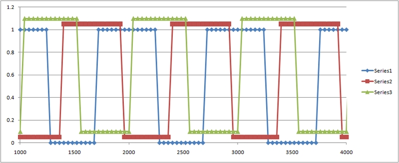
Very good, that looks reasonable. See attached plot.
It looks like the 6 state Hall sequence is:
5 1 3 2 6 4, then repeats. So that means when we read Halls=5 we are near 0 degrees, Halls=1 -> 1/6 of a cycle, Halls=3 -> 2/6th of a cycle, , Halls=2 -> 3/6th of a cycle,etc...
I've built this into a lookup table. See the attached C program called HallCommutate.c. Running the program should properly commutate the motor for a fixed voltage amplitude. Try it and see.
One good test for proper commutation is to stall the motor with your hand. Then move the motor to all angles by hand and verify that the torque is relatively constant at all positions (and in the same direction).
Incidentally what type of motor is this? It seems to have a lot of poles since your program goes through 4.8 cycles (120*40/1000) and you said the motor only rotated 1/2 of a rev. Most motors only go through about 2 cycles/rev.
If that works then the next step might be to also monitor the Hall sensors and keep track of position (which can also be used to determine speed). Actually if you move two of the Hall inputs to single ended encoder inputs on KFlop or KMotion then I think the Halls will count much like a quadrature encoder (but with 60 degrees phase difference instead of 90 degrees, so odd/even counts will be different in size). If you have 10 cycles/rev that will result in 40 counts/rev. I bet you could even servo to that.
Thanks
TK
| Group: DynoMotion |
Message: 316 |
From: Azd Md |
Date: 4/18/2010 |
| Subject: Re: Hall Sensor [2 Attachments] |
Thanks a lot, The motor is Maxon Flat motor 251601, It was bought with the wrong driver and I have to fix mess.
After testing the program the motor rotates but with a speed more than before but still low. How to increase the speed. I wnat to test the motor speed at its nominal value, shall I increase the implitude or the angle??
Regards
--- On Mon, 19/4/10, Tom Kerekes <tk@...> wrote:
From: Tom Kerekes <tk@...>
Subject: Re: [DynoMotion] Hall Sensor [2 Attachments]
To: DynoMotion@yahoogroups.com
Date: Monday, 19 April, 2010, 3:02 AM
Azd,
Very good, that looks reasonable. See attached plot.
It looks like the 6 state Hall sequence is:
5 1 3 2 6 4, then repeats. So that means when we read Halls=5 we are near 0 degrees, Halls=1 -> 1/6 of a cycle, Halls=3 -> 2/6th of a cycle, , Halls=2 -> 3/6th of a cycle,etc...
I've built this into a lookup table. See the attached C program called HallCommutate. c. Running the program should properly commutate the motor for a fixed voltage amplitude. Try it and see.
One good test for proper commutation is to stall the motor with your hand. Then move the motor to all angles by hand and verify that the torque is relatively constant at all positions (and in the same direction).
Incidentally what type of motor is this? It seems to have a lot of poles since your program goes through 4.8 cycles (120*40/1000) and you said the motor only rotated 1/2 of a rev. Most motors only go through about 2 cycles/rev.
If that works then the next step might be to also monitor the Hall sensors and keep track of position (which can also be used to determine speed). Actually if you move two of the Hall inputs to single ended encoder inputs on KFlop or KMotion then I think the Halls will count much like a quadrature encoder (but with 60 degrees phase difference instead of 90 degrees, so odd/even counts will be different in size). If you have 10 cycles/rev that will result in 40 counts/rev. I bet you could even servo to that.
Thanks
TK
|
| | | |
|
| |
|
| |
|
| | | |
|
| | | |
|
| | | |
|
| | | |
|
| | | |